AMTR is a micro anechoic chamber for phased array development, suitable for Ku and Ka bands. The AMTR is a fully Ku operational system that can be used by design engineers straight away, without the need to book a timeslot for use and no need to set it up. The AMTR is a very useful design tool for antenna, SW and HW engineers for quick development, testing and characterisation. A control CLI user interface and Antenna GUI control interface is used to configure the AMTR setup, and can plot and extract all measurement data in various formats.
Features
- Full Ku band coverage 10.7 – 12.75GHz and 13.75 – 14.5 GHz.
- Suitable for antenna size: 64 to 256 elements (Ku), and up to 512 elements (Ka).
- Simultaneous Rx or Tx measurements.
- Simulations radiation of the two polarizations.
- Tracking emulation.
- Single-axis polarization positioner + 45° to -90°
- Single-axis azimuth positioner for AUT ±90°
- 30dB dynamic range control of the transmitted and received signal.
- 78cm free space range.
AMTR is suitable for the following radiation measurements:
- beam width.
- sidelobe levels.
- cross-polarization.
- beam steering (pointing error).
The AMTR is not intended for accurate antenna measurements, but it is an invaluable resource for the antenna designer to:
- Develop and optimize calibration algorithms.
- Optimize algorithms for cross – polarization improvement.
- Design and optimize algorithms for beam steering.
- Design and optimize algorithms for tapering.
- Test the antenna performance under the modulated waveform.
- Perform single cut Antenna Pattern measurements.
- Perform cross – polarization measurements.

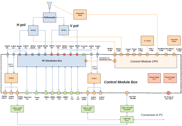
AMTR Top-Level Block Diagram
